

Tools needed:
14mm wrench
15mm wrench
19mm wrench
Large Flat blade screwdriver
soft mallet or wood block
Engine Barring Tool
Long 1/2″ drive wrench
Torque Wrench
feeler gauge
NOTE: The Cummins Midrange Performance Tool Kit (P/N 3399869) contains all of the tools required for an oil and oil filter change, a fuel filter change, and a valve-lash adjustment – including the special barring socket. Also available from Cummins is a 6 in-lb valve adjust torque wrench which sets a consistent load on the feeler gauge. This tool is handy, but not necessary.
Engine Barring tool sources: Cummins # 3377371; Snap On # YA9565; KD tools # 3824
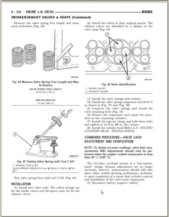
Valve clearance should be adjusted when the engine is cool (below 140 F or 60 C).
Intake Clearance: 0.010″, 0.254 mm
Exhaust Clearance: 0.020″, 0.508 mm
Service Interval : 24,000 miles
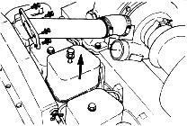
with a soft mallet or wood block – Do not pry the cover loose.
passenger side.
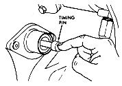
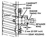
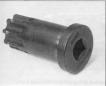 Insert the barring tool into the bellhousing hole. Insert a 1/2 drive wrench into the barring tool, and turn the crankshaft slowly, while watching the valve train. Press the timing pin to locate Top Dead Center (TDC) for cylinder No.1.
| Note: The timing pin is located at the back of the gear housing and below the injection pump. Fitting the timing pin into the hole in the crankshaft is tricky, watch the valve train until the #1 exhaust valve closes, then turn the crankshaft about 90 degrees. If the timing pin will not engage, spray it with some penetrating oil to loosen it. |
 |
| 5. | When the pin engages the hole in the camshaft gear, cylinder No. 1 is at TDC on the compression stroke. Be sure to disengage the timing pin after locating top dead center. |
 |
| 6. | Adjust the clearance for these valves: #1 – I & E#2 – I#3 – E#4 – I#5 – E
|
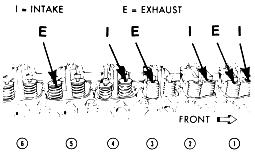 |
| Adjust Intake valves for 0.010″ clearance Adjust Exhaust Valves for 0.020″ clearance
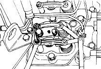
From the Cummins B series Operation and Maintenance manual: The adjustment is correct when some resistance is felt when the feeler gauge is slipped between the valve stem and the rocker lever. |
|
|
| 7. | Tighten the lock nut, torque to 18 ft-lb (24 Nm) and check the valve lash again. When the feeler gauge slides between the valve stem and the rocker lever with “some” resistance, the clearance is correct. | |
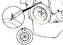
| 8. | Mark the crankshaft pulley and rotate the crankshaft 360 degrees. Caution: Make sure the timing pin is disengaged. Rotating the crankshaft with the timing pin engaged will beak the pin and can result in engine damage. |
 |
| 9. | Adjust the clearance for these valves:#2 – E#3 – I#4 – E#5 – I#6 – I & E
|
 |
| 10. | Tighten the lock nut, torque to 18 ft-lb (24 Nm) and check the valve lash again. When the feeler gauge slides between the valve stem and the rocker lever with “some” resistance, the clearance is correct. | |
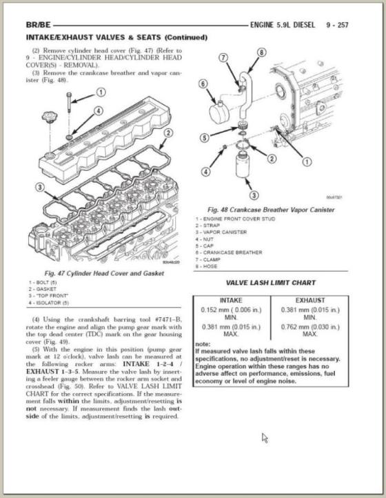
| 11. | Inspect the rubber o-rings on the bolts and replace any o-rings that are cracked or damaged. The valve cover gaskets are usually OK and may be reused many times. If any are damaged, be sure to replace then with the black gaskets, not the gray gaskets that appear similar. Install the valve covers and tighten the capscrews to 18 ft-lb (24 Nm).. |
 |
| 12. | Install the plastic cover or crossover pipe on appropriate models. |
A short version:
-
Let the engine cool 4 hours and remove the valve covers.
-
Use the alternator bolt to turn the engine backwards.
-
When a rocker arm is not on the lift lobe of the cam, adjust the intake valves for 0.010″ clearance and the exhaust valves for 0.020″.
> Loosen the lock nut
> Adjust for the correct clearance – a slight drag will be felt on the feeler gauge
> Torque the locknut to 18 ft-lb.
> Recheck the clearance – the drag on the gauge should be the same.
-
Continue turning the engine and adjusting valves until all have been completed (put a small plastic sandwich bag on each valve when it has been done).
-
When adjustment has been completed, remove the plastic bags from the valves and replace the valve covers
Another short version:
Put the engine on #1 compression stroke, use the timing pin to locate this the first time then mark your harmonic balancer. Set the first 3 valves, skip 2 valves, set 2 valves, skip 2 valves, set the next valve. Rotate engine 360 degrees, until your mark lines up again, now you will be on exhaust stroke of #1 cyl., compression stroke of #6 cyl. Skip the first 3 valves, set the next 2 valves, skip the next 2 valves, set the next 2, skip the next valve, set the last 2.
Another short version:
Crank engine around with ratchet wrench and 15mm socket on one of the bolts that holds the pulley on the vibration damper, until # 5 (the next in the firing order) intake valve goes down and just starts to come back up,STOP! Adjust # 1 intake and exhaust valves at this time. Make sure the feeler gauge just sides under the rocker arm smooooothly after you have re-tightened the lock nut. If its too tight or too loose, try to loosen the lock nut and the adjuster together until the lock nut is loose and then adjust the screw either tighter or looser and retighten them together again. It will take a little time to catch on to it, but you will. The intake valve is in the front and the exhaust is in the back on each cylinder. Now, turn the engine over until # 3 ( the next in the firing order) intake valve goes down and just starts to come back up,STOP. Adjust # 5 the same way you did # 1. Now turn engine over until # 6 (next in order) intake valve starts back up,STOP adjust # 3. Just follow the firing order back to # 1.
Another short version:
Here’s a tip for doing valve lash adjustment that will make it go faster…
1. Turn over the motor with a 7/8″ socket on the alternator pulley. One other thing, to locate TDC @ #1, watch #6 until it’s at crossover (one rocker going up, the other going down at the same time). This is called the “companion cylinder” method. Adjust the proper valves, then rotate the engine over until #6 is at TDC, which means #1 will be at crossover. Gap the intake valves at 0.010″ and the exhaust at 0.020.”
When at TDC for #1, check: Intake 1, 2, and 4 Exhaust 1, 3, and 5
When at TDC for #6, check: Intake 3, 5, and 6 Exhaust 2, 4, and 6
Heres some data from a repair manual

[thanks to dodgeram.org and TDR used with permission]

5 Trackbacks
[…] http://dieseldatabase.com/b-series-v…ustment/?id=62 Red_Rattler's Sig:JAKE DIESEL BOMBERS SUPER MODERATOR CLICK HERE FOR SPONSORSHIP INFORMATION CLICK HERE TO BECOME A PREMIUM MEMBER AKA BOMBARDIER _________________________________________ 03Flame Red 2500 4×4 QuadCab Handshaker HO,Kore HP Kit, Smarty REVO, AIRDOG II 165, Banks TechniCooler, K&N FIPK, MBRP Cool Duals 6inch tips, GunSlinger Pistol Grip Shifter, SRT Inine 6 Hood, Jacobs Brake 95 2500 4X4 Ext Cab Handshaker "BUCKN' BADGER" […]
[…] adjustment: http://dieseldatabase.com/b-series-v…ustment/?id=62 __________________ 97 Ram 2500 / 5.9ctd /NV4500/241DHD Custom Intake Tube+ BHAF, Pump Tuning, […]
[…] articles are your friend http://dieseldatabase.com/b-series-v…ustment/?id=62 __________________ 97 Ram 2500 / 5.9ctd /NV4500/241DHD Custom Intake Tube+ BHAF, Pump Tuning, […]
[…] in 10minutes without feeler gauges). With a solid tappet it takes a little more time LOL http://dieseldatabase.com/b-series-v…ustment/?id=62 Specs are 010 intake 020 exhaust, if you forget, its also stamped on the engine data plate on the […]
[…] http://dieseldatabase.com/b-series-v…ustment/?id=62 If this link works it should answer all your questions. Make sure you buy your cover gaskets at Cummins or genosgarage or they may not las as long as the factory ones. __________________ 92 D250 custom made bed, 190 inj., 16cm , electric cooling fan, 2nd gen air horn, 5spd. 97 2500 4X4 DDP 40 HP, no 8 fuel plate, homemade 3" intake horn, BD converter […]