
Throttle cable failure has been common on 1994 – 1998 12 valve diesel engines, usually after about 30,000 miles on the cable. I am now on my third cable, and am curious to see if the new design will be more reliable. Twice I have managed to replace my cable in the nick of time and I know of several people who have been stranded by cable failure. It is a good idea to carry a spare cable for roadside repair. If you have the older cable WITHOUT a plastic sheath (i.e. the metal cable is exposed – it will probably be frayed) at the throttle lever, carry a spare or have it replaced with the new design. If you do not, you will probably have cable failure sooner or later.
When I did this last time, I skipped several steps in the instructions and found that other parts of the instructions would not work on my 1994 model. My notes are added in italics.
Throttle cable repair procedure:
Record Radio Station presets. (skipped)
Disconnect and isolate battery negative terminals from both batteries. (skipped)
Remove the stainless band clamp at airhorn to intercooler hose connection. Move the metal intercooler tube out of the way from the throttle cable mounting plate. (skipped)
If equipped, disconnect the TPS electrical connector and remove the TPS (vehicles equipped with automatic transmissions or CA emissions).
Remove the three clips that secure the engine harness and temporarily secure the harness to the top of the injector pump.
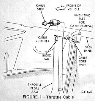
From inside the vehicle, remove the plastic cable retainer by unsnapping it from the end of the pedal arm (Fig 1).
From inside the vehicle, pinch tabs on both sides of the plastic cable housing retainer and push the cable through the dash panel (the firewall) (Fig 1).
Remove the throttle cable socket from the primary bell crank lever ball stud by using a 3/8″ open end wrench positioned between the bell crank lever arm and cable socket and prying the cable socket off the ball stud. (I used a large screwdriver to do this)
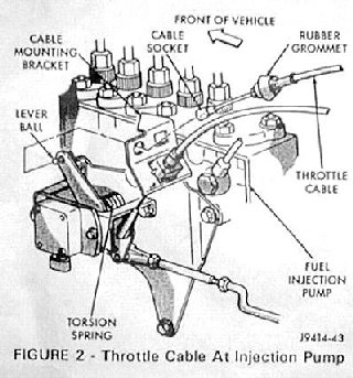
Work the throttle cable grommet rearward through the mounting bracket (Fig 2). Two small screwdrivers can be used to assist in pushing the grommet out of the bracket. Remove and discard the throttle cable.
If the vehicle is equipped with an automatic transmission, unclip and remove the throttle valve cable from attachment on the secondary bell crank lever by sliding the plastic snap cap end forward.
If the vehicle is equipped with a speed control, unclip and remove the speed control cable from attachment on the secondary bell crank lever by sliding the plastic snap cap end forward.
Disconnect and remove throttle rod from secondary bell crank lever by removing the retainer clip and carefully prying throttle rod end off of ball stud with a small screwdriver.
Rotate secondary bell crank lever clockwise until spring tab contacts the TPS bracket. Then rotate the lever an additional 1/2 inch and pry breakover spring tab inward with a screwdriver until the spring tab is no longer resting on and clears the tang on the bell crank lever when the lever is released (Fig 3).
Remove the E-clip and washer that retains the secondary bell crank lever.( it WILL try to escape!)
Remove and discard the secondary bell crank lever.NOTE: Make sure neoprene washer positioned under the lever remains on the TPS shaft.
Install revised secondary bell crank lever onto the bell crank lever shaft. Install the washer and secure the lever with the E-clip.
Connect breakover spring to secondary bell crank lever.
Position one end of the spring onto the tang of secondary bell crank lever.
Rotate bell crank lever clockwise until tang on lever passes or clears the other end of the spring.
With a screwdriver, pry the end of the spring outward and release the bell crank lever (Fig 3). (you have to hold your mouth just right to get this to work) NOTE: Both ends of the spring are positioned on each end of the two tangs on the secondary bell crank lever assembly.
Install throttle rod onto the ball stud and insert the retainer clip.
Verify that the throttle rod is properly adjusted by measuring the distance between the center of the lever ball and the rear face of the cable mounting bracket (Fig 5). The specification for this dimension should be 5.0″ (126.5 mm). If the throttle rod exceeds the specification, refer to the 1997 Ram service manual pages 14-95 and 14-96 for the adjustment procedure.(Note: There was no Fig 4)
If equipped, attach the speed control cable by sliding the end of the cable onto the nail head stud attachment on the secondary bell crank lever and snap into place.
If equipped, attach the throttle valve cable by sliding the end of the cable onto the nail head stud attachment on the secondary bell crank lever and snap into place.
Feed revised throttle cable through the rear of the mounting plate (Fig 2) until the grommet locks into position on the bracket.
Position the throttle cable end over the ball stud on the secondary bell crank lever and snap into place.
Insert the opposite end of the throttle cable through the dash panel opening until the tabs on the cable housing retainer snap into place (Fig 1).
From inside the vehicle, snap the plastic throttle cable retainer into the upper end of the pedal arm. NOTE: Align the index slot on the plastic cable retainer to the index tab on the pedal arm (Fig 1).
Re-position the engine harness on the engine and secure the harness by inserting the plastic fasteners into the three metal clips on the engine.
Verify that WOT can be achieved by having an assistant push the accelerator pedal to the bottom of its travel. Push rearward on the secondary bell crank lever while monitoring for movement. If the secondary bell crank lever moved prior to bell crank lever breakover (the point at which the return spring winds up), loosen the cable mounting plate and rotate the plate until WOT can be achieved. Tighten the mounting plate to 18 ft-lbs (24 Nm). Confirm that the bellcrank returns to full idle when the pedal is released. NOTE: If WOT cannot be achieved, the throttle rod linkage adjustment may need to be re-adjusted. See the 1997 Ram service manual pages 14-95 and 14-96 for the procedure.
If equipped, install and adjust the TPS. Refer to the 1997 service manual pages 14-133 and 14-134 for TPS adjustment procedures. Another method for adjustment is to utilize the DRB III to monitor the TPS voltage from the “SENSOR” screen. The TPS should be adjusted to 1.0 volts +/- 0.20 volts with the throttle linkage at an idle position.
Install the intercooler tube onto the air horn outlet. Properly position the band clamp and tighten the clamp nut to 50 in-lbs (6 Nm). (skipped)
Connect both battery negative cables. (skipped)
Reset the clock and radio. (skipped)
Additional Note:
One TDR Member reported that after changing his throttle cable, the engine ran at full throttle with no pressure on the accelerator pedal.
His problem: “I didn’t remember that the “ear” on the new bell crank had to go into the little slot on the secondary bell crank that has the throttle rod attached to it.”
What happened: “I had a HELL of a time getting the spring on the first time I tried it, had to use a wire to get it pulled around far enough…I didn’t have the “ear” in the slot on the scondary bell crank. I had it in ??front of the secondary, which meant it had to be pulled around about a 1/2″ too FAR. Then I got everything back together, started it…WOT with the pedal completely off of the floor… The second try on the other side of secondary bell crank…still WOT… saw one of my customers who was driving his 12V, flagged him offer and discovered that it was supposed to go in the little slot on the secondary bell crank…WALLAA…”