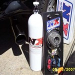
Post Your Successful Diesel Mods At Dieseldatabase

Have you completed a successful mod on your diesel truck? and did you take pictures and discovered tips that might help others? Your post is welcome here. All you have to do is register on this site. Then contact us via the the contact form on the ABOUT page (see menu), letting us know you […]

Stewart Warner B779 Add-On Shift Light Install Sheet

Click the link below for the pdf version of Stewart Warner Add-On Shift Light Install Sheet Stewart Warner Add-On Shift Light Install Sheet [thanks to Stewart Warner used with permission]

24V Cummins Engine Diagram

24V Engine Diagram [click on image for larger version]

Installing Upfitter Switches in 2005 and Newer Ford Super-Dutys

If you want to add a few aftermarket options to your new Ford Super Duty, Ford Motor Company makes things easy for you. One of the options you can select from the factory is the “UPFITTER SWITCH” option. This is a bank of four switches, with fuses and associated relays, that provide two 30 amp […]

Stewart Warner B806 Exhaust Temp Gauge Install Sheet

Click the link below for the pdf version of Stewart Warner B806 Exhaust Temp Gauge Install Sheet Stewart Warner B806 Exhaust Temp Gauge Install Sheet [thanks to Stewart Warner used with permission]

Stewart Warner B758 Ultra Alert Light Install Sheet

Click the link below for the pdf version of Stewart Warner B758 Ultra Alert Light Install Sheet Stewart Warner B758 Ultra Alert Light Install Sheet [thanks to Stewart Warner used with permission]

FASS Install

This link is the pdf file for the FASS Install guide. [Thanks Diesel Performance Products] FASS Install

Fast Idle Modification

This mod article will walk you through the steps of installing a Fast Idle Switch. Application: ’05 6.0 PSD with Torque Shift Transmission.   Tools Required: 10mm socket with extension and ratchet Wire striper, cutter, crimp tool At least 5 feet of wire (12-14 gauge, color is user defined) 2 sets of butt or spade […]

Universal Joint Replacement

Work Performed on an ’03 CTD The ujoint pictured below is the factory joint that I just took out. My rear drive shaft was replaced the 1st time to the dealer under warranty. Then they replaced the ujoints again after that, making a total of 3 sets of factory joints within 75,000. When I first […]

Pyrometer Installation

See Universal Installation Guide for Installation on Turbo Down Pipe 1. Remove turbo from exhaust manifold. 2. Stuff a small shop towel or rag 4 to 5 inches into the rear exhaust manifold passage (see pic below) through the turbocharger mounting flange. This is to prevent chips from entering the manifold while drilling and tapping. […]

Mixing Gasoline with Diesel

My wise old mechanic who has worked on Mercedes for years told me that if I put one gallon regular gas to a diesel tankfull after about every four tanks that it would perform essentially the same job as a fuel injector cleaner at a fraction of the cost. I would like to hear a […]

Old 12v Cummins Boost Guage Installation

1. A hole must be drilled and tapped into the intake crossover pipe for a boost source. 2. Remove the hose from the intake crossover pipe and push a rag well into the pipe past the point to be drilled and tapped. This will prevent chips from entering the engine. 3. Drill through the back […]

Cummins 12V Idle Adjustment Q&A

Subject: [RTML] Cummins idle speed How do I adjust the idle speed on my Ram diesel? The idle speed seems too high. First, trace the accelerator linkage to the connection on the fuel pump. With the ENGINE OFF have someone floor the accelerator and watch the fuel arm move. The best position I can describe […]

Another 24V Lift Pump Replacement Procedure

This is how I replaced the lift pump on my ’99 QC, 4×4. Not sure what variations may or may not accure on other models. Parts list…………..New lift pump, lift pump wire pig tail, banjo bolts washers (8), dielectric grease and approx 1/2 gallon of clean diesel. Tools ………. 3/8″ drive ratchet, 3 or 4 […]

Superchips 3705 Chart and Installation

24V Cummins Fueling System Diagram

1998 CTD No Description 1 Fuel Transfer (Lift) Pump 2 Fuel Return Line (to Fuel Tank) 3 Fuel Supply Line (Low Pressure, to Engine) 4 Fuel Heater 5 Water-in-Fuel (WIF) Sensor 6 Fuel Filter / Water Separator 7 IAT Sensor 8 Map (Boost) Sensor 9 Fuel Drain Manifold 10 CKP Sensor 11 CMP Sensor 12 […]