With the addition of the 33″ BFG’s and the Detroit Locker, I could feel some wheel hop, with the only real mod being the addition of the 70 hp chip. Anticipating the increased horsepower my PSD will be putting out, I decided to add traction bars to the rear axle. Trying to save money for other projects, I decided to make my own. I read a post on TheDieselStop.com where someone (sorry, I don’t remember who it was, I just wanted to make a note that it is not my original idea) made their own traction bars using tractor implement third member bars. So, that’s what I did.
Overview of Project:
The implement third member top link is an ideal product to make a traction bar. It has swivel mounts on each end, adjustability to set the desired preload on the traction bar, and is very heavy-duty. Although it does not have the more desired Heim joints, for the money it makes a great system.
This project does require fabrication skills and the appropriate equipment, but it is fairly straight forward. A cutting torch (or better yet a plasma cutter!), grinder, welder, and equipment to drill large holes are the equipment needed. The idea here is to use a stock top link, cut it in half and lengthen it, and make brackets to mount it to the truck frame and axle. The traction bars are mounted to the bottom side of the axle to prevent the axle from rotating forward. The stresses on this part of the axle usually dictate the use of a ladder type of construction, but I don’t see how the straight pipe design I use could fail. Beefy stuff!
Materials Used:
- 2 – Adjustable top links, from Tractor Supply, $ 16.75 each.
- 4 feet of 1 1/4″ schedule 40 steel pipe, about $ 6.50.
- 3 feet of 3″ x 1/4″ flat steel stock (some extra when done), about $ 6.75.
- 3 feet of 3″ x 2″ x 1/4″ steel angle, about $ 13.50
- 4 – 3/4″ x 4″ grade 5 plated bolts, nuts, and washers, about $3.00
- 4 – 1/2″ x 1 1/2″ grade 5 plated bolts, nuts, and washers, about $ 2.00.
Total cost of project is about $65.
Making The Bars & Brackets
My local steel supplier did not have any ‘C’ channel the width of the swivel ends of the top link, so I bought some 1/4″ steel angle and flat stock to make my own. I used what was left of the flat stock to make the brackets that mount to the rear axle.
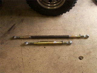
This photo shows the comparison of the stock top link (bottom) and the lengthened bar (top). I simply cut the bar in half, and welded in a section of 1 1/4″ schedule 40 pipe. The total length of the bar from eyelet to eyelet is about 42″.
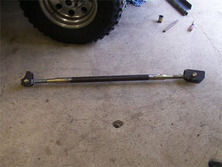
This is a pic of the finished traction bar with the brackets attached at each end.
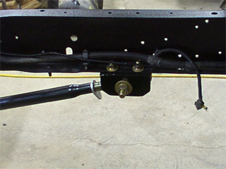
The ‘C’ channel I had to make using steel angle and flat stock, then bolted to the frame using existing holes. I used 1/2″ bolts to the frame, and 3/4″ bolts at each end of the links. All grade 5 stuff.
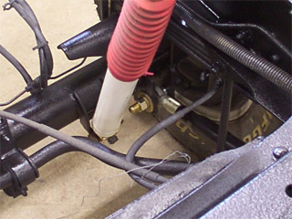
The brackets that attach the traction bars to the axle. I just used some flat stock, cut a curve on one side to match the radius of the axle tube, and welded two of them between the u-bolts to match the width of the bar eyelets.
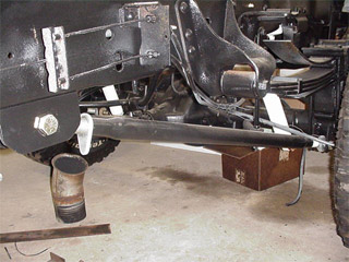
The completed install showing mounting on the truck frame and at the axle.
Results:
I was a little skeptical at first as to how the ride would be. But there is plenty of travel for everyday driving. What I did notice was, that if I was to haul a heavy load, I’d need to manually adjust the load on the bars or they might break right off the frame or axle. To solve this, the bars should be quite a bit longer, so they are more horizontal than what they are. I could not have them any longer because my exhaust exited in front of the rear tire, and that was in the way. I now have stacks on the truck, so there are no more obstructions. I’ll probably lengthen them some day, but for now they seem to work great.
Happy wrenching.

