CAUTION:If you intend to operate the engine over 3200 rpm, you should replace the engine valve springs with a heavy-duty type. If you do not have heavy-duty exhaust springs installed please call PDR for further instructions.
Estimated completion time: (First time installer) 1.5 hours
Things you will need to complete this project:
1. 7/16″ deep socket
2. 3/8″ drive and ratchet
3. 10mm six point socket, 3/8″ drive w/extensions
4. 8mm, 6-point 1/4″ or 3/8″ drive socket
5. Pliers and Pencil magnet
6. Medium to large flat-blade screwdriver
7. Slim, long, flat-blade screwdriver
8. Vernier Calipers
9. 8mm Allen wrench
10. 7/8″ Socket
11. Tape or clean towel to block openings
12. Fender covers (optional)
Cleanliness counts! Clean engine to keep debris and foreign objects from entering engine.
1. READ all the directions before beginning the installation.
2. Set parking brake. Automatic transmissions must be in park, manual transmissions must be in neutral.
3. Protect paint and batteries with covering
4. Using a 7/16″ deep socket, loosen lower clamp on upper intake connection hose and slide lower clamp off of hose and down the steel tube out of the way.
5. Remove the six bolts holding the air intake connection and dipstick tube in place using a 10mm 6-point socket. The bolts are different lengths. They must be replaced in the correct position.
6. Remove intake manifold connection and hose as a unit. The gasket must not be damaged in this process. It can be reused but must be replaced if damaged.
7. Cover the air tube and manifold openings to keep foreign objects from falling into them.
8. There are three bolts holding the fuel shutoff solenoid & bracket to the injection pump, two on top of the AFC housing & one at the back of the pump. Remove these three bolts & the hairpin that holds the solenoid rod to the pump linkage.
9. After removing solenoid you will see a plug nut, using a 7/8″ socket, loosen this plug nut. You will have to hold the linkage over to one side so you can get enough clearance to totally remove plug nut.

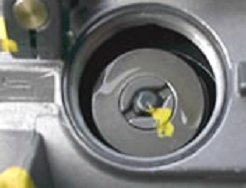
10. Bar (roll) the engine over until the governor spring adjusting nut comes into view, center it in the hole. Note the position and mark it.

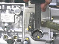
11. Using the Vernier calipers, measure the distance from the top of the governor stud to the top of the governor spring adjusting nut. Record this measurement for the reassembling.

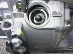
12. Remove the spring retainer and all inner springs (leave large spring in place). Remove inner spring seat assembly at the bottom of the bore and remove any shims that are installed. Check for shims stuck to the springs or seats. Do not reinstall shims as are they are no longer required. Use only the springs contained in your new kit. Do not reuse any of your original springs other than the large spring left in place at the beginning of this step.
13. Install new lower spring seat and springs. Install upper spring seat and adjusting nut. Adjust to the measurement noted at disassembly.
14. Bar engine over until opposite governor spring set is in position. Repeat steps 12-13.
15. Reinstall plugnut, fuel solenoid and bracket.
16. Remove air tube and manifold coverings.
17. Reinstall intake manifold connection and hose.
18. Start engine and check idle speed. A variation of plus or minus 50-60 RPM is normal and we recommend that this be adjusted using the idle screw. Go for a test drive and enjoy!
[thanks to piersdiesel.com used with permission]

2 Trackbacks
[…] break otherwise. The GSK is added to the injection pump. The follwing link shows how it is done. http://dieseldatabase.com/12v-cummin…or-spring-kit/ Pac Brake 10029 GOVERNOR SPRING KIT dodge 12v engine 1994-1998 All it does is allow your truck to […]
[…] to me looks like getting past my hydroboost and antilock brake parts. This shows how it is done. http://dieseldatabase.com/12v-cummin…or-spring-kit/ __________________ 1997 3500 club cab Automatic 3.54 gears towing and camper package. Still […]