
This documentation is intended to be used as a visual overview only and is not meant to be used as a replacement for a service manual. Please consult your Dodge service manual for complete instructions on the removal and re-installation of an injection pump
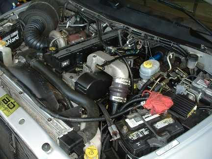
The truck in this project is a 2000 Dodge Ram 3500 Quadcab 4×4 equipped with the 235hp Cummins diesel engine (engine order code ETC) and the NV4500 5-speed manual transmission. The fuel injection pump died without warning at 119K miles. This truck is also outfitted with a BD turbo-mounted exhaust brake, Fleetguard BHAF with Outerwears prefilter, and dual exhaust. Power upgrades come in the form of a Van Aaken box. This particular VP44 pump wire has never been pierced nor has any fuel conditioner been added to the fuel. The low-pressure transfer (lift) pump was replaced around 105K miles with Cummins P/N 3990105 when the previous lift pump died. The lift pump delivers a steady 14psi at idle, and drops to 10psi at WOT. A Westach 0-16psi fuel pressure gauge mounted in the cab is used to monitor fuel pressure. The schrader/banjo bolt at the VP44 is where fuel pressure is sensed on this truck.
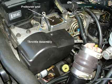
The VP44 replacement begins just like an injector upgrade. Disconnect both batteries, then start by removing the intake air manifold, preheater grid, and throttle assembly. This will open up the work area and allow you to gain access to the injection pump.
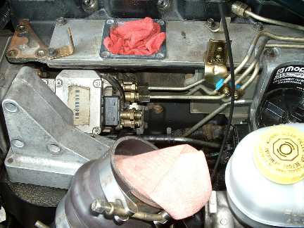
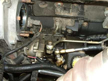
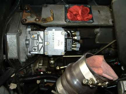
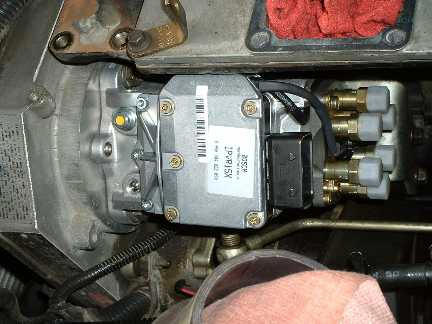
Here we have removed the 9-way electrical connector from the Fuel Pump Control Module (FPCM) on the injection pump and have also started to remove the high-pressure fuel lines. One of the best tips I received before starting this project is to remove the hard lines in 2 bundles of 3 while leaving most of the isolators in place. First, remove the outermost (closest to driver-side fender) cluster of 3 lines as one group, then remove the remaining 3 lines as one group.
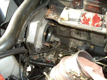
This picture shows the injection pump has been removed. I barred the engine using the alternator nut to place the pump/gear keyway at the 12 O’clock position. You will need a gear puller to separate the injection pump shaft from the injection pump gear, then you can remove the 4 injection pump mounting nuts as well as the 2 bolts securing the injection pump lower mounting bracket to the engine block and then you can remove the injection pump from the gear housing. BTW, you will need a 27MM socket to remove the injection pump shaft nut.
Another view of the engine bay with the VP44 injection pump removed. Now would be a great time to change the camshaft position sensor (CMP).
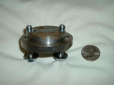
Here is a picture of the Blue Chip Diesel gear puller that was used to separate the injection pump gear from the injection pump shaft. It came complete with washers and the metric bolts used to thread into the injection pump gear. It is a pretty trick little unit and presses only against the end of the injection pump shaft so there is no chance of cracking the cast gear cover.
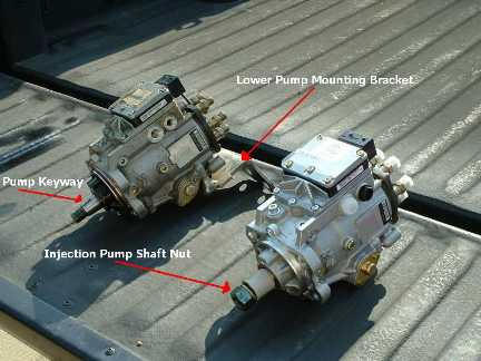
Here is a shot of the old and new pumps together. The old/dead pump is on the left, the new reman unit is on the right. The new pump came with the “tamperproof” Torx-head bolts installed in the pump cover.
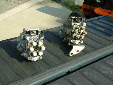
Another side-by-side shot of the pumps. Notice the pump mounting bracket is still attached to the bottom of the old pump on the right. This bracket must be removed from the old pump and secured to the new pump before installation. The bracket is mounted to the pump with 2 Torx-head bolts.
Here we can see the new injection pump installed into the gear housing. We used a mirror to help line up the pump keyway and the injection pump gear together. The o-ring on the new pump is a little tough to get seated in place, just have patience and it will eventually cooperate.
Another shot of the new pump installed. Basically, the rest of the installation is the reverse of the removal; Install the hard lines in 2 bundles of 3, install the low-pressure feed line and fuel return line to the injection pump, connect the 9-way FPCM connector, throttle assembly, preheater grid and intake air manifold. Another good tip I received before starting this project is do NOT crack the throttle on the truck until all the air is purged from the system, just let the truck run rough at idle until all the air is removed.
[Kent is with nwbombers.com]