
THIS BULLETIN SUPERSEDES TSB. 18-10-94 DATED JUL.. 22, 1994. THE PART NUMBER FOR THE ENGINE TIMING TOOL PACKAGE HAS BEEN CHANGED TO SPX MILLER #6860.
Models: 1994 (BR) Ram Truck
Symptoms:
Excessive white exhaust sake or lack of power.
Diagnosis:
Using the Mopar Diagnostic System (MDS) or the Scan Tool (DRB II or III) with Diagnostic Procedure Manual (No.81-699-94003), verify that all engine system are functioning as designed. If Diagnostic Trouble Codes (DM’s) are present, record them on the repair order for future reference and repair as necessary. If no codes are present and all system are functioning correctly, inspect for the following possible causes and repair as required:
1. Engine Running Too Cold: Check coolant temperature by placing radiator thermometer in radiator. Replace thermostat if necessary.
2. Low Coolant Level; Check coolant level in the reserve tank and radiator, correct as required.
3. Verify with the owner that the proper starting procedure is being used. Refer to the starting and operating procedure, Pages 46 – 57, listed in the 1994 New Dodge Ram Cummins Turbo Diesel Owners Manual (Publication No. 81-326-9422).
4. Verify with the owner that the fuel quality meets recommendations. Refer to Pages 29 and 30 in the Owners Manual.
5. Inspect the air cleaner for any restriction. Replace as required.
If all system are functioning correctly proceed with the following repair.
Tools Required:
1 Engine Timing Kit – 5.9L Diesel – Miller No. 6860
Consists Of (Miller#):
1 Socket, Delivery Valve 6840 1 Barring Tool 7471B
1 Adapter, Dial Indicator 6842 1 Brg./Thrust Wa. 6862
1 Tip, Dial Indicator 6843 1 Dial Indicator 6859
1 Gear Puller – L-4407A
Parts:
1 4778483 Delivery Valve Washer
Repair:
This bulletin involves verifying that the injection pump timing pin is properly aligned in the fuel pump and resetting the pump timing, if required, to provide peak performance.
1. Thoroughly clean the engine and fuel system before attempting to remove any parts. Pay special attention to the fuel injection pump. Use compressed air to remove any water remaining on the fuel pump after the cleaning process.
Caution: Do not allow any dirt, debris, or paint chips to enter the fuel system while it is open. If any foreign material of any type is allowed into the pump, lines, or injectors during this process, it could result in an injection pump or fuel injector malfunction.
Locate TDC cm cylinder #1.
2. Remove the rubber access plug located in the rear flange of the engine an the exhaust manifold side.
Tip: Removing #1 cylinder valve cover and barring the engine clockwise until- the exhaust valve starts to close will make locating engine TDC faster as described later in step 4.

3. Insert the barring tool through the access hole and into the flywheel housing.
4. While holding tension on the timing pin (toward front of engine), slowly, rotate the engine with the barring tool. Hold a slight rearward (pushing) pressure on the barring tool and rotate the tool counterclockwise until the timing pin drops into the machined hole in the back of the camshaft gear.
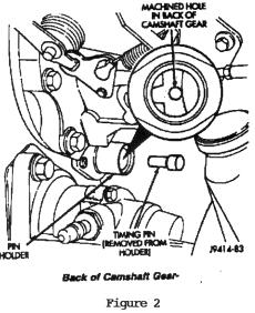
When the pin aligns to the gear, the engine is now at the TDC position (compression stroke) at cylinder #1 (Figure 2). Place a paint mark on the damper to indicate TDC (use speed sensor as a reference to locate this mark) . Remove the pin to prevent damage when barring the engine in later steps.

NOTE : THE PIN IS LOCATED ABOVE THE POWER STEERING PUMP, BELOW AND TO THE INSIDE OF THE FUEL INJECTION PUMP, ON THE REAR OF THE CAM GEAR HOUSING (FIGURE 3).

Check injection Pump Timing:
5. Remove #1 fuel injection line from the fuel pump (Figure 4).
Caution: Do not bend the fuel line. Bending the line will cause line or injector failure.

6. With the engine at TDC, loosen but do not remove, the front #1 delivery valve holder using special socket, Miller P/N 6840 (Figure 5).
Note: There is an external O-ring on the holder to help prevent debris from getting into the pump. This may create a slight resistance as the holder is unscrewed.

7. Remove the delivery valve holder by carefully tipping the holder outboard with one hand while using your other hand to hold the spring, fill piece, and any shims from slipping out of the holder. Place these as an assembly on a clean surface out of the way (Figure 6).

8. Using a magnet, remove the two piece delivery valve assembly from the pump. Place these pieces on the clean surface with the delivery valve holder (Figure 7).

9. Using a pick, remove the copper delivery valve washer from the top of the pumping element. Be careful not to scratch the top of the plunger/barrel assembly during this process. Discard the used delivery valve washer. A new washer, P/N 4778483, will be used during reassembly (Figure 8).
10. Install the dial indicator adapter, Miller P/N 6842, in place of the #1 delivery valve holder and tighten finger tight.
11. Loosen the set screw on the dial indicator adapter and install the dial indicator, Miller P/N 6859, into the adapter. Position the dial indicator to read between 7.0 and 9.0 mm and tighten the set screw (Figure 9).
NOTE: The dial indicator is capable of measuring from -20.00mm IFT. The small inner dial is marked in increments of 1 mm. The larger outer dial is marked in increments of 0.01 mm. One revolution of the outer dial is equal to 1 mm. The inner dial only indicates 0-10 mm, but will rotate twice as the indicator goes through the full range.

12. Using the engine barring tool, Miller P/N 7471B, rotate the engine in the direction opposite normal direction of engine rotation counterclockwise from front of engine) 1/4 turn or until you see the dial indicator reading stop dropping. This is the inner base circle of the injection pump cam. Zero the indicator and note the reading on the small inner dial (Figure 10).
CAUTION: Be sure the timing pin is disengaged before rotating the engine to avoid damage to the timing pin.
13. Rotate the engine clockwise slowly to TDC. Note the pump lift setting on the dial indicator (Figure 10).
IMPORTANT: All 1994 Cummins Diesel Engine vehicles equipped with a manual transmission should be set to 12.5 degrees engine timing. All automatic transmission equipped vehicles should be set to the timing specified on the engine data plate. Refer to the engine “Timing-TDC” listed on the Engine Data Plate and compare it to the Pump Lift Setting/Engine timing listed below.
| 5.4 mm | 11.0 |
| 5.5 mm | 11.5 |
| 5.6 mm | 12.0 |
| 5.7 mm | 12.5 |
| 5.8 mm | 13.0 |
| 5.9 mm | 13.5 |
Adjust Injection Pump Timing
14. If a change in injection timing is required, remove the oil filler tube and adapter elbow from the front of the gear housing.

15. Place a magnet on the end of the shaft and remove the shaft nut (use the barring tool to keep the engine from rotating), (Figure 11). Install bearing and thrust washer, Miller P/N 6862, and reinstall the shaft nut.
CAUTION: If the input shaft nut and washer are removed, without using a magnet, the nut or washer may drop down inside the timing gear cover, requiring significant disassembly of the engine on order to recover them.
16. Slowly rotate the engine clockwise until reaching the required lift setting on the dial indicator. The injection pump should rotate with the engine since the pump gear is still locked to the injection pump shaft.

17. With the injection pump at the correct plunger lift setting, use gear puller, Miller P/N L-4407A to pull the injection pump gear off the taper of the injection pump input shaft. Leave the gear puller installed (Figure 12).
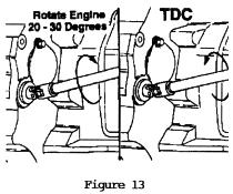
18. Rotate the engine 20 to 30 degrees counterclockwise, then rotate the engine back clockwise to TDC. This removes backlash from the geartrain (Figure 13).

19. Loosen, but do not remove, the gear puller bolts. Using the gear puller, rotate the pump gear counterclockwise by hand while pushing the gear onto the pump shaft. This will remove backlash between the injection pump and camshaft gears (Figure 14).
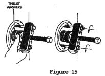
20. Hand tighten the input shaft nut. Remove the gear puller (Figure 15).

21. Torque the shaft nut to 15 Nm (11 lb. ft.) to seat the shaft taper. Then remove the nut and bearing & thrust washer, Miller P/N 6862. Reinstall the nut. Hold the engine from rotating (use the barring tool) and torque the nut to 195 NM (144 lb. ft.), (Figure 16).
CAUTION: USE A MAGNET TO MAKE SURE THE NUT AND WASHER DO NOT DROP INTO THE TIMING GEAR COVER.
22. Repeat Steps 12 and 13 to verify that the final timing setting is correct. If the setting is not correct, repeat steps 14, 15, 16, 17, 18, 19, 20 and 21.
23. Remove the dial indicator and adapter from the injection pump.
CAUTION: The following installation and torquing procedure must be followed exactly. Improper installation of the delivery valve will result in damage or leaks.
24. Install a new copper delivery valve washer, P/N 4778483, into the fuel pump.
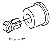
25. Install the delivery valve assembly on top of the sealing washer (Figure 17).
NOTE: The two pieces of the delivery valve must be assembled as shown in Fig 17.
26. Lubricate the threads and clamping surface of the delivery valve holder with a few drops of SAE 90 hypoid gear oil. Do not lubricate the copper delivery valve washer or its seating area.

27. Install the delivery valve holder assembly taking care not to displace the delivery valve spring, fill piece, or any shims (Figure 18).
NOTE: The delivery holder must be assembled as shown in Fig 18.

28. Pre-torque the holder to 40 NM (29 lb. ft.). Next, in one motion, torque the holder to 115 NM (85 LB. FT.). (Figure 19).
29. Install remaining engine components removed during the timing process. Leave the injector side of the #1 high pressure fuel lines loose to facilitate ‘bleeding’ the air out of the system.
CAUTION:The pressure of the fuel in the line is sufficient to penetrate the skin and cause serious bodily harm.
30. Crank the engine until fuel is observed at the #1 injector. Tighten the high Pressure line at the injector. Start the engine and check for leaks.
31. Type the necessary information on the Authorized Modification Label and attach the label near the VECI Label.

Notes:
Policy: Reimbursable within the provisions of the warranty
Time Allowance:
Labor Operation No: 14-45-08-90 Verify Injection Pump Timing – 2.1 Hrs.
Labor Operation No: 14-45-08-91 Verify Injection Pump Timing and Reset – 3.1 Hrs.
Failure Code: AM – Authorized Modification Label
NOTE: This procedure is good for all 12 valve Cummins B engines.
[thanks to DodgeRam.org used with permission]
3 Trackbacks
[…] http://dieseldatabase.com/p7100-inje…-timing/?id=39 __________________ 2006 3500 SRW (converted), SLT SBC 12CB 3250. Pac Brake 95 C&C LWB, 315K mile beater […]
[…] and read all that …. then you may be ready to set your timing. Here's one to get you started: http://dieseldatabase.com/p7100-inje…-timing/?id=39 __________________ 97 1500 with 95 12v .040 over 5 speed 3:54 CAI 4" straight … boost […]
[…] truck. Mopar1973Man's Dodge Cummins Articles – P7100 Injection pump – Confirming Stock Timing http://dieseldatabase.com/p7100-injection-pump-timing/ Timing in 40 minutes (P7100) This shows how to make one timing tool cheaply. timing question […]