A. THERMOCOUPLE INSTALLATION – The R650 Thermocouple mounts into a 1/4″ pipe thread. If the exhaust manifold is already drilled and tapped, install the thermocouple at that location. If none is provided, make a 3/4″ hole in the exhaust pipe, not more than 6″ below the exhaust-manifold-to-exhaust-pipe connection and weld the R680 bushing into the the exhaust pipe – NOTE the bushing should not be installed backwards – the R650 thermocouple will only install into one side of the bushing. On a Dual Manifold: Install one R650 thermocouple into each exhaust manifold or exhaust pipe as above.
NOTE: Banks predrills a tap on their Turbo Down Pipes – The location of the tap is farther down than the 6″ listed below which Banks feels is the optimum area when coming off the turbo.
B. LEADWIRE INSTALLATION – Single Manifold: The R660 lead wire assembly and the R650 thermocouple are supplied with screw and ring terminals for assembly convenience. Connect the longer red leadwire to the to the red thermocouple wire and the shorter yellow wire to the yellow thermocouple wire with screws and nuts provided. Cover these connections with protective sleeves provided. Route the other end of the R660 leadwire assembly to the pyrometer, making sure that the leadwire is clear of obstructions that might cut or otherwise damage it. (If it should become necessary to replace any of the terminal ends – use crimp or clamp types only – NEVER solder terminals to the wires.) Dual Manifold with Single Gauge: Run an R660 from each thermocouple to a DPDT switch. The switch will then toggle from one engine bank to the other on the same gauge.
C. PYROMETER INSTALLATION: Remove dampening wire(s) across the meter terminals. Mount the pyrometer through the instrument panel or use or use mounting bracket at the desired position. Connect the light wires to the existing instrument light switch (12 VDC.)
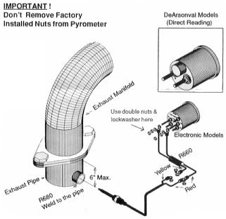
Single Scale Pyrometers: R602, R604, R606 and R607. Connect the R660 leadwire to the pyrometer making sure that the yellow leadwire is connected to the positive (+) terminal and the red wire is connected to the other terminal. (if the leadwires are connected backwards, the pyrometer will read backwards.) Use double nuts and lockwasher provided to attach the leadwire to each stud and tighten the gauge in the panel. Do not loosen the nuts that are already on the pyrometer gauge terminal studs. The pyrometer has been set to ambient (room) temperature at the factory and should not require further adjustment.
Dual Scale Pyrometer R624. Connect the R660 leadwires from the left exhaust pipe to the left meter and from the right exhaust pipe to the right meter, making sure that the yellow leadwires connect to the positive terminals.
NOTES:
1. If the pyrometer light is too bright, substitute a 28V lamp (GE# 656.)
2. If the pyrometer is slow or erratic, check the leadwires and thermocouple with an ohmeter for continuity and check the leadwires for resistance (wire resistance is .23 ohms per foot per wire). Also check for oil, grease or looseness at the terminals. The connection must be clean and tight.
3. The pyrometer is calibrated for use with 6 to 15 foot leadwires.
4. When properly installed, the accuracy of the system will be within 2% at 1200 degrees F under average operating conditions.