
If you want to add a few aftermarket options to your new Ford Super Duty, Ford Motor Company makes things easy for you. One of the options you can select from the factory is the “UPFITTER SWITCH” option. This is a bank of four switches, with fuses and associated relays, that provide two 30 amp and two 10 amp circuits. With the upfitter switch option, you can add a winch, lights, strobes, two way radios, or whatever else powered by the truck’s electrical system you can think up. There are many other uses for these switches that other users have developed, so don’t be afraid of asking for ideas!
You may think that you missed out on this option if you bought your Super Duty off the lot. Not so! You can buy the individual Ford authorized factory parts from your dealer, or “The PowerStroke Shop” offers the authorized Ford factory parts in a upfitter switch kit, which includes the switches, a wiring harness with a central junction box (CJB) which mounts under the passenger glove box, and a filler tray that fills the space left for those truck owners who do not have the Tow Command option installed.
Beginning the installation
So the big brown truck has brought your package of parts, or you have visited your local Ford dealer and bought all of the Ford stock items and you are ready to start your installation. Let’s go over the items needed for a successful installation.
Tools needed:
Small metric socket set, 10 mm and below
Other items needed:
Two M5 x 20 .80 fine thread bolts and lock washers to hold the Central Junction Box bracket in place, these bolts fit the supplied speed clips that are on the bracket. Hex heads are easier to tighten with a socket set.
Optional:
Fish tape and electrical tape to feed wiring harness.
Liquid refreshment.
Items you wish to connect to the switches.
Approximate time of installation:
One to two hours. This is the whole installation from tear down to clean up and test. Take time and do the job right.
To start:
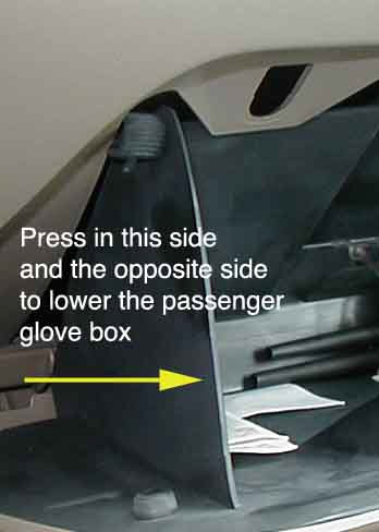
Remove everything from both the driver and passenger side glove box. (Some refer to the driver side glove box as the ashtray) Tilt the door of the passenger side glove box down fully by pressing the sides of the passenger side glove box, until the tab stops clear the sides of the dash opening. You may have to do this one side at a time. Lower the glove box door until the door hangs completely down. Repeat the process for the driver side glove box.
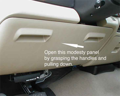
Remove the modesty panel that covers the fuse panel from beneath the steering column by pulling on the handles toward you, and set it aside.
If your truck has the Tow Command brake controller, you will find there is a tray to the left of the controller. If your truck is not equipped with the Tow Command system, you will have two small trays installed.
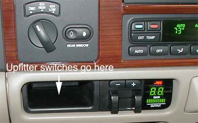
Trucks equipped with Tow Command modules will look like the picture above. For trucks without Tow Command, another tray similar to the one on the left will be in its place. The upfitter switches replace the left tray.
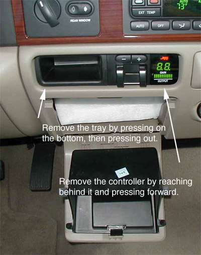
Both trays are removed by reaching under through the driver side glove box, pressing firmly up, and then out. The Tow Command controller is removed by pressing the back of the controller firmly, which will release the retaining clips. This will expose the space where the upfitter switches are installed.
Starting at the passenger side glove box, guide the wires through to the fuse panel. Ensure that the wiring harness clears the travel of the passenger side glove box before committing to a particular path for the wiring. Make sure that the connector for the upfitter switches can be accessed through the opening you just made. Stay clear of the travel of the driver side glove box. Look for additional sound deadening insulation
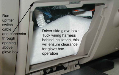
(white material) if it is there, tuck the wiring harness behind it. You will note that there is a pushpin connector on the wiring harness that fits into a pre-drilled hole in the dashboard frame to hold the wiring in place. Find the hole in the frame and press the pushpin in place.
Using these pins makes it easy to make sure the wiring will remain in place. Once the wiring has been routed, mount the Central Junction Box mounting bracket to the dashboard frame using the bolts you purchased.
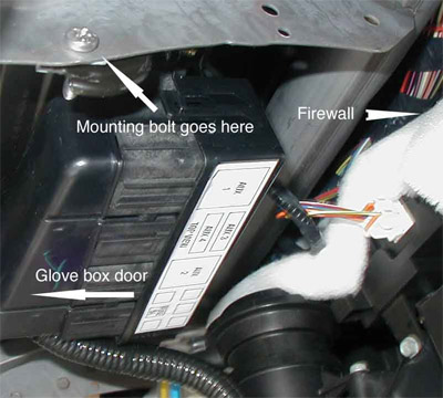
The mounting bracket bolt on the right side of the bracket is horizontal, and goes through a hole in the dashboard frame closest to the front of the dashboard and the glove box door, through the mounting bracket and the speed clip.
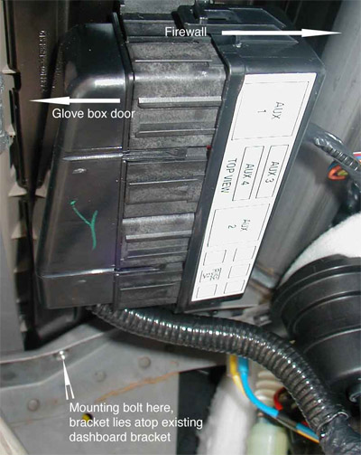
The mounting bracket bolt on the left side is vertical, and the mounting bracket sits on top of the existing dashboard frame, with the bolt going through the frame and into the mounting bracket and speed clip.
Feed the upfitter switch connector through the dashboard opening left by the tray you removed previously. Connect the upfitter switch wiring connector to the back of the upfitter switch. It is indexed and will only go in one way. Take the upfitter switch and connected wire and press the assembly into the dash opening on the far left side until the switch snaps in.
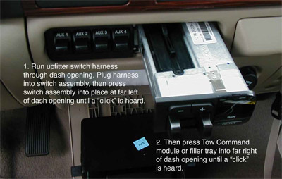
If you have Tow Command, press the controller in the opening on the far right side until it snaps in. If you do not have a Tow Command module, The PowerStroke Shop provides a replacement tray in the kit that fills the void left by this installation, making the completed installation look factory installed. Fill the void with this tray by placing it on the far right of the opening and pressing it in until it clicks. Look under the dashboard for the factory ground point on the dashboard frame, located to the right of the steering column, to the left of the driver side glove box.
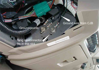
Attach the ground wire connector by removing any ground bolt, adding the ground wire, making sure the tang on the connector fits into the slot, and then add the ground wire that was there previously. Replace the ground bolt.
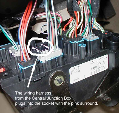
The final part of the installation connects the upfitter switch circuits to the factory wiring harness. Remove the fuse panel out by removing the four bolts that hold it in place. You may have to lift up and then out to get the fuse panel to come free of the dashboard. To the left of center of the fuse panel assembly, you will see an eight pin male connector. It is indexed so that the connector from the central junction box wire loom can only go in one way. Plug the wiring harness connector here by pushing firmly until you hear a “click”.
You now have the four blunt cut wires left to connect to your chosen accessories. To help you plan which accessories can be connected to each switch, use the following chart:
| Switch | Circuit Number | Amp Capacity | Wire Color |
| AUX 1 | 1936 | 30 | Orange / Light Green |
| AUX 2 | 1933 | 30 | Orange |
| AUX 3 | 1934 | 10 | Orange / Yellow |
| AUX 4 | 1935 | 10 | Orange / Light Blue |
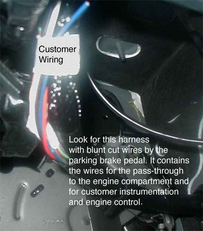
There is no need to drill through the firewall to wire accessories to the outside. Ford has provided four 14-gauge wires that lead from the passenger compartment to the outside of the cab. They are located in a bundle behind the fuse panel above the parking brake. There will be a tape marked “CUSTOMER ACCESS” around this wire bundle. There will be 11 wires total in the harness. The other wires are used to control such options as power-take-off (PTO) and provide additional feedback instrumentation. See the illustration below:
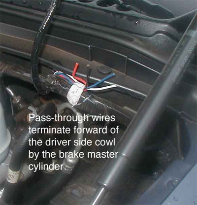
These pass-through wires terminate in the engine compartment in front of the cowl on the driver’s side, behind the brake master cylinder. Any wiring attached to these blunt cut wires should be made with moisture-resistant connections, and the wiring should be of an heat resistant type with polypropylene insulation per Ford recommendation. Ensure that the wiring is kept well away from the heat sources of the engine and turbocharger.
They are identified as follows:
| Circuit Number | Color Code | Wire Gauge | Function |
| 1353 | Red | 14 | Customer Defined |
| 1487 | Dark Blue | 14 | Customer Defined |
| 1495 | White | 14 | Customer Defined |
| 1501 | Black | 14 | Customer Defined |
Ford recommends bare metal crimped butt connectors; flow soldered, covered with adhesive filled heat shrink tubing for all connections.
When all wiring is complete, ensure that no wires will chafe or interfere with pedal operation, then bolt in the fuse panel and reinstall the modesty panel by placing the bottom in first, catching the hooks at the bottom, then pressing at the top of the panel to engage the snaps.

FORD PART NUMBERS FOR UPFITTER SWITCH COMPONENTS:
Upfitter switch assembly- 5C3Z-13D730-AAA
Central Junction Box and wire loom assembly – 5C3T-14A303-P260G
Filler tray (housing) 5C3Z-2513546-CAA
Parts available separately from your local Ford dealer. All parts are available in one kit as the “05UPFITTERSWITCHKIT” from Wabash Ford, Indianapolis, Indiana aka The PowerStroke Shop Check the web site for current pricing and shipping information.
One Use for an Upfitter Switch:
The High Idle Modification:
While many Super Duty owners enjoy their trucks for their towing capacity and their creature comforts, most Super Duty trucks are built for work. The engine management computer program that is resident in Super Duty trucks with power-take-off transmissions (PTO) is also a part of the computer program in EVERY Super Duty. A simple matter of applying 12 volts to a circuit, along with setting the parking brake and having the transmission in Neutral or Park, will bump the idle speed to 1200 RPM. Changing any of these states reverts the truck’s engine to normal idle until all of the parameters are again met.
What does a high idle accomplish? Among other things, should you need to have your truck idle for an extended length of time, high idle reduces the possibility the engine “wet stacking” or developing excess carbon deposits on the injectors. In colder weather, it can reduce warm up time. In warmer weather, increased coolant flow and airflow across the radiator due to the increased engine fan speed can reduce the chance of overheating at idle. It can speed battery charging. High idle can maintain passenger compartment heating and cooling. But what was Ford’s purpose for designing this feature into the engine management system?
Here’s one example. Super Duty trucks are used in vehicle wrecker fleets. In order to drive the hydraulic pump that makes the tow dolly move up and down to lift a stricken vehicle, the engine speed on the Super Duty needs to be increased. An operator could put a foot on the accelerator, put a stick on the accelerator, or flip a switch and let the truck’s computer do the work. Or another. The utility bucket trucks that have a lineman repairing electric lines from a hydraulic lift arm. The hydraulic pump is driven by the truck’s engine.
There are many other reasons that you may think of for using this modification, which simply uses Ford’s own engine computer management to control your diesel’s idle speed. This modification comes from data compiled from Ford Motor Company files, and should in no way compromise the warranty on any vehicle.
How to make the high idle circuit
Use an upfitter switch, because that is one of the uses Ford designed them for. As the amperage required for control of the PTO function is very low, use AUX 4, a 10-amp circuit.
As you remember, the blunt cut wires for the upfitter switches are at the rear of the fuse panel. Select the Orange/Light Blue wire, which is controlled by the AUX 4 switch and relay. Behind the parking brake, look for another bundle of blunt cut wires. Ford calls this the Customer Access or CASC bundle (the bundle is there so the trucks can be modified by Ford approved body manufacturers). There will be 11 individual blunt cut wires, including four pass-through wires for the upfitter switch circuits. (See the picture above) You are looking for one, a purple/light green wire. As there is not enough wire to reach from the fuse panel to the CASC bundle, you will have to make a small jumper cable. Four to eight inches, depending upon your finger dexterity, should be long enough.
Connect the Orange/Light Blue blunt cut wire from the upfitter switch wiring harness to the Purple/Light Green wire in the CASC bundle, using butt connectors and the jumper cable.
In order for the high idle to work, the engine management system must sense the following states:
Parking brake set
Transmission in Park or Neutral
Service brake not engaged
Press the parking brake, place the transmission in Park or Neutral, and then start the engine as normal. To test the circuit, bring the AUX 4 switch up. The idle speed of the engine should increase to 1200 to 1250 RPM, even rising to as high as 2400 RPM depending upon the state of battery charge. Release the parking brake. The idle speed should return to normal.
Acknowledgements:
Ford Motor Company, Truck Body Builder Advisory Service QVM Bulletin Q-117 “2005 F Series Super Duty Upfitter Switches”
Ford Motor Company, Truck Body Builder Advisory Service, “2005 Super Duty F-Series Electrical Wiring Customer Access Circuits”, page 170
Ford Motor Company, Truck Body Builder Advisory Service, “Power Take Off Applications” 2005
The Ford logo is a trademark of the Ford Motor Company. This web page is not sponsored by or endorsed by the Ford Motor Company.
Text and illustrations copyright 2005
Richard L. Ray
All rights reserved. No part of this work may be reproduced without the express consent of the author.
richardray@cox.net