
Several people on the TDR website showed interest in learning more about the work involved in replacing a broken timing gear housing from damage caused by the upper dowel pin working its way loose.
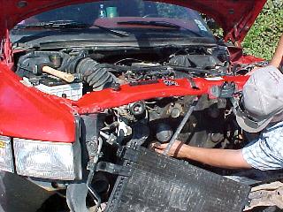
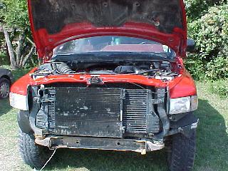
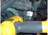
You first remove the bumper, fan, radiator and loosen the A/C condenser. It is possible to remove the intercooler without breaking the A/C lines and losing the charge of Freon as shownbelow. You must be very careful though. The harmonic balancer and electrical sensor are being removed here.
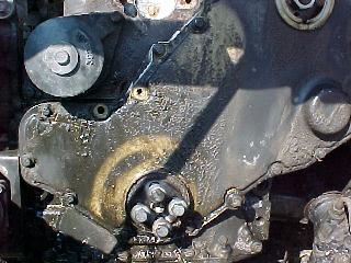
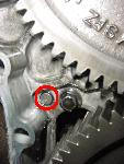
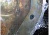
This illustration shows the timing cover with the idler pulley removed. The crack caused by the dowel pin is always under the idler pulley and cannot be seen until it is removed.
This crack is the first sign of internal damage.
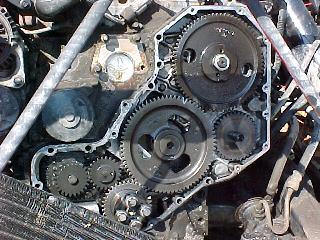
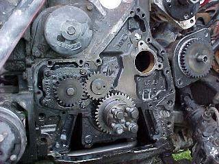
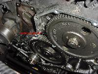
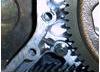
You then remove the case cover and expose the internal timing gears. This is a good time to rotate the engine until the timing marks on the camshaft and crankshaft gears line up. You can see by the ‘V’ mark on the camshaft gear that this engine needs to be rotated almost a full 360° to align with the white mark on the crankshaft gear at the two o’clock position.
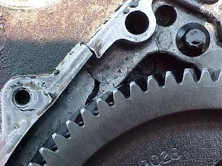
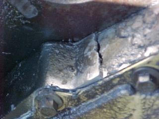
With the cover removed you can see more of the damage caused by the dowel pin. On this particular engine, no visible damage was done to the timing gears.
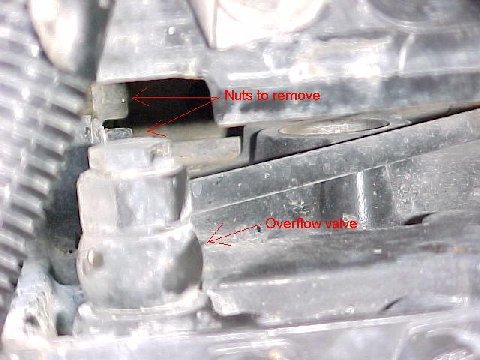
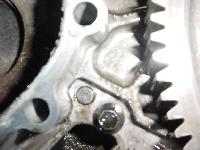
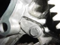
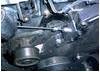
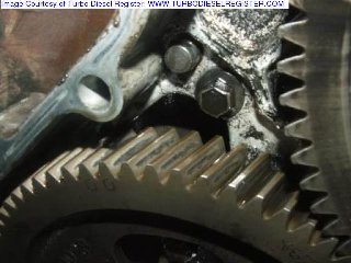
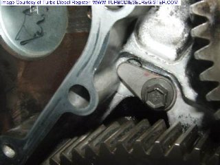
Now the easy part is over with. removing the timing houseing is a bit more involved. The vacuum and power steering pump assembly can be removed with two bolts. The vacuum pump gear does not need to be removed, it slides out through the back of the housing. Four nuts that hold the injection pump to the timing housing must now be removed. The two outside nuts are easy to access, but the inner two are difficult. Below is a picture of the inner two nuts. A severely bent hand wrench will access the top nut. The bottom nut requires more imagination.
The next step is to remove the camshaft. This requires removing all six valve covers, rocker assemblies and push rods. There obviously isn’t room to extract the pushrods from the #5 and #6 cylinders. Dodge has conveniently left two holes in the cowl of the truck just for this purpose. The holes are filled with two rubber plugs. To gain access to these plugs, the windshield wipers and plastic cowl must be removed.
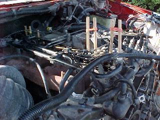
You will need twelve 1/2″ dowel rods cut one foot long for the next procedure. Each rod needs to be tapered down to a sharp point. Begin the taper 1″ from the end of the rod. Now cut a 1″ slit in that taper. You then drive the dowel rod into the tappets and pick them up off the camshaft. A rubber band will hold the dowel rods up and keep them from falling back down. It’s very important for the dowel rods to be secured to the tappets firmly. The camshaft is likely to hit the tappets while being removed and reinstalled. If one of the tappets falls off the dowel rod, you will need to remove the oil pan to get it out!
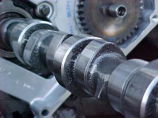
Now you can remove the camshaft. It will take a steady hand to slide it out. Be gentle. When the camshaft is positioned correctly it slides out easily.
Now the timing housing can FINALLY be removed. Now you just need to clean off the old gasket and reassemble.
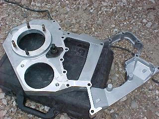
The four studs that mount to the injection pump as well as the timing pin need to be moved from the old housing to the new housing as shown here.
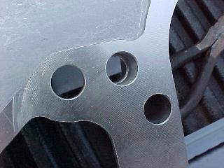
This photo was taken from the back side of the new case. You can see that the hole for the dowel pin is now necked down so the pin can no longer work its way out. Too bad this wasn’t included in the original design.
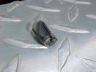
We used a magnet to retrieve the dowel pin out of the oil pan before reassembly. It looks as if the pin was ground on for quite a while by some of the gear. Notice the blue marks from heat!
Now you reassemble in the reverse order. Make sure you install the intercooler BEFORE the radiator. Isn’t that right Cord? :)
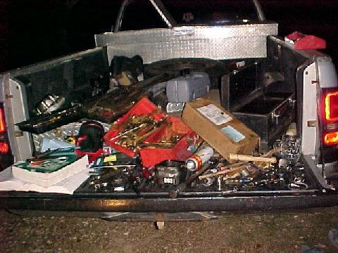
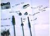
This final picture was taken of the bed of Cord’s truck after the job was complete. We didn’t realize just how many tools the job required until we saw this.
I hope this helps some of you understand the work involved in replacing the timing housing. This was meant as a general overview and not a set of step by step instructions.
JIG
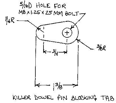
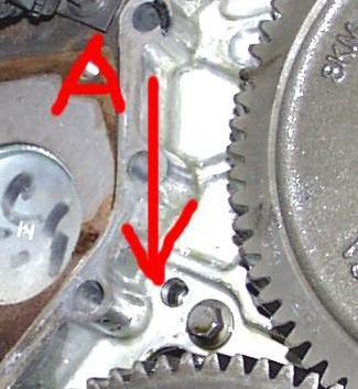
R.ebel posted the drawing below with dimensions for a KDP blocking tab for the 1997 engine. Some years of the 5.9 have a slight step in this area of the gearcase, but the tab will still work with some minor modification. The small end of the tab is designed to lock into the contours of the gearcase to prevent any rotation of the tab. Arrow “A” on bboxall’s photo points to the KDP’s home. The retainer tab goes under the bolt head just to the lower right of the KDP hole. Always install a new main seal before replacing the timing cover.
The tab can be made from thin steel stock or cut from a 2″ dia fender washer with a 1/4″ or 5/16″ hole. The bolt is M8 X 1.25 X 25mm.
| Part Numbers: | |||
| Cummins | Dodge | NAPA | |
| Dowel Pin: | 3900257 | 04429257 | NA |
| Gear cover gasket: | 3918673 | 5012290AA | NA |
| Seal kit: | 3804899 | 4638719 | Chicago Rawhide 24868 |
| BOLT (8mm X 1.25 X 25mm) | 3900631 | ||

KDP tab photos sent by Ernie Little
Dowel pin location.
KDP location.
Before tab installation.
After tab installation.
Blocking Tab Installation Instructions:
(Thanks to Mike Beatty for adding corrections and tips)
Timing Cover Removal
1. Remove fan assembly with a 36mm or 1 7/16″ wrench. The thread is left hand and you may need to whack the wrench with a hammer to break the nut loose. In many cases, a drift punch and hammer are are the easiest tools to use for breaking the nut loose; place the punch on the driver side of the fan nut face and hit the punch with a hammer.
2.Remove the fan belt. (3/8″ ratchet)
3.Remove the 6 bolts that hold the fan pulley on and then the 4 that hold the fan mount to the block.
4.Remove oil fill tube and adapter. (13 mm wrench)
5.Remove vibration damper. (15 mm wrench)
6.Remove the bolts that hold the gear cover to the gear housing. (10 mm wrench)
7.Gently pry the cover away from the housing, taking care not to mar the gasket surfaces.
8.Clean the old gasket residue from the back of the gear cover and front of the gear housing.
Tab Installation
1. Remove the timing gear housing bolt closest to the KDP. (10 mm wrench)
2. Position the tab so that it covers the dowel pin hole and is wedged between the cover bolt boss and the rib cast into the housing.
3. Install the original bolt through the tab and torque to 18 ft-lbs. (10 mm wrench) Use Locktite 205 or similar on the bolt threads to prevent the bolt from loosening. While you are there, check the torque on the other housing bolts. If any are loose, apply lockitite to the threads and torque the bolt 18 ft-lbs.
Timing Cover Installation
1. Lubricate the front gear train with clean engine oil.
NOTE: Mike Beatty reused the seal and gasket with no leaks. Use a thin plastic, like what is on a loose leaf binder, and tape it together to make a tapered sleeve.Just be very careful installing the crank seal over the snout. Oil the snout and sleeve with synthetic oil, and it will slide right on. It also helps to use several studs to guide the plate on and hold it until you get the other bolts started. If you do it this way, you can skip to step 10.
2. Use a hammer and punch to drive the old seal out of the cover.
3.Thoroughly clean the front seal area of the crankshaft. The seal lip and the sealing surface on the crankshaft must be free from all oil residue to prevent seal leaks. The seal is designed to transfer a film of teflon to the dry, clean crank surface after initial startup
4.Apply a bead of Loctite 277, or equivalent to the outside diameter of the seal. (Note: Some use 242 blue or 205 Red)
5.Install the seal into the rear of the cover using a plastic hammer and the alignment/installation tool provided in the seal kit. To prevent damage to the seal carrier, hit the alignment/installation tool alternately at the 12, 3, 6 and 9 o’clock positions.
6.Install the pilot from the seal kit onto the crankshaft.
7.Using the pilot as an alignment tool, install the cover and a new gasket.
8.Install the cover bolts and tighten to 24 Nm (18 ft. lbs.) torque. (10 mm wrench)
9. Remove pilot tool.
10.Install the oil fill tube and mounting bolts. Tighten the bolts to 43 NM (32 ft. lbs.). (13 mm wrench)
11. Slide the small black plastic dust seal (included in the seal kit) over the end of the crank and up snugly against the crank seal with the flat side out. Install the vibration damper. DO NOT tighten the bolts to the correct torque value at this time.
12. Install the fan mount to the block and the 6 bolts that hold the fan pulley on.
13. Raise the belt tensioner to install the belt. (3/8″ ratchet)
14. Tighten the vibration damper bolts to 125 NM (92 ft. lbs.). (15 mm wrench) Use an engine barring tool to keep the engine from rotating during tightening operation.
15. Install the fan assembly. 36mm or 1 7/16″ wrench
Dowel Pin Stabilization Instructions From Cummins:
The dowel pin itself can be replaced if desired or Locktite can be used to hold it in place, without having to replace the pin or gear housing assembly. Inspection and securing of the timing cover dowel pin:
1. Remove the damper, pulley and gear cover from front of engine.
2. Tap on the dowel pin with a flat punch to insure that it is seated in the bore.
3. Clean all the oil from area with solvent and dry completely.
4. Apply some wicking type Locktite #290 on the dowel pin and let the Locktite cure.
5. Reinstall the cover with a new seal and gasket.
6. Reinstall damper and pulley.
From Mike Beatty:
Either cover the openings to the pan or use a magnet when putting the tab in place to keep it from falling into the oil pan. Also, setting the timing is easier while the gear cover is off becauseloosening the gear is much easier and you can clean the gear and shaft better.
Comments collected from several TDRoundtable threads:
Dieselnerd: I bought a bolt that was about 1/4″ longer and used high strength Loctite on the bolt. I made the tab out of a 2″ fender washer with a 1/4″ hole, had to use a rat tail file to enlarge it slightly to fit the metric bolt. I used a hacksaw to cut the tab to size. I used a new gasket and seal on the cover. I used Permatex spray on both sides of the gasket. The seal was a real pain like Rebel said. Kept going in crooked. I finally bolted the damper back over the seal tool that came with the seal and pressed it in that way. That method pushes it almost all the way in to where it should be. The cover is bolted on but not tightened down. You put the seal installer into the cover to center the hole in the cover over the crank and then tighten the bolts. The service manual is very specific about this. Then you slip a plastic sleeve into the seal to keep it from deforming as it slips over the crankshaft end. You tap the seal with the installer to get it started and then pull out the sleeve.
Joe G.: I put the seal in the cover first. The kit comes with a tool to set the depth. I used my vice and pressed it right in. The manual says use some blue LocTite so I did that. There is also a tool to put the seal on the crank. I put the tool in the seal in the cover before installing the cover. I made a couple of alignment pins out of some long old screws so that the cover was straight. It was easy to put on.
Frank Simkowski: The Cummins front crankshaft/timing housing seal kit consists of three components: 1) the seal 2) an installation tool 3) an alignment/installation sleeve that slips over the crank snout for slipping on the newly sealed timing cover. The alignment/installation sleeve is then removed after the timing cover is fastened in position. The seal is a Teflon laydown lip type. They must be installed on a DRY, CLEANED, NO-OIL RESIDUE crank snout surface. They are designed to transfer a film of teflon to the dry, clean crank surface after initial startup.
HEMI®Dart: You don’t need to drain the coolant or take off the upper radiator hose. I didn’t even need to take the shroud off. You can pull out the fan from the top if you are careful. You will need to push the upper radiator hose towards the firewall to make room for the clutch & fan assembly to come out. I used 0.030″ steel to make my tab. It was like a metal sawzall blade type material. Hard.
Retainer Bolt for the Killer Dowel Pin
|
 |
Drill jig components. You only need to supply the bolt, and drill. |
 |
Drill jig installed on the timing case. | |
 |
Drilling the hole. | |
 |
1/4 -20 by 1″ flathead hex bolt installed. Case cover was removed for the photograph. | |
 |
Bolt installed. Case cover was removed to show how the bolt keeps the KDP from escaping.. |
CPFF’s Instructions: Using The Drill Jig To Neutralize The Killer Dowel
Loosen the fan (1 7/16″ wrench, Left Hand Thread) and remove the radiator overflow bottle. On my ride the Horton fan and shroud must come out together as one unit. If you can get your fan out past the shroud, do it now. It will save you time. If not, continue with the following: Release the windshield washer bottle on the driver’s side. Unbolt the radiator shroud. Push the top of the shroud towards the motor and pull the fan out between that and the radiator. Move the shroud from side to side to sneak the protruding ears past the radiator hoses. To help with this, bend the top center of the shroud toward the motor-this makes the shroud a little narrower.
Now remove the serpentine belt. Remove the two bolts that hold the alternator on. The bottom rear nut is 15mm, the front bolt is 13mm. Without disconnecting any of the wires, set the alternator up on the rubber intake hose. Remove the 6 bolts that hold the fan pulley on and then the 4 that hold the fan mount to the block.
Put a shop towel over the top of the bottom pulley, then clean the area to the right of where the fan mount was located. (That’s the area where you are going to be drilling.) Remove the 2 bolts from the front cover, put the drill jig on and replace the bolts. Go underneath the truck and hook the regulator to the breather hose. Set the regulator to a maximum of 2 lbs.
Using a low-powered drill-such as a cordless-put the smaller of the two bushings in the jig and drill through the casting with the drill provided. The aluminum casting where you are going to be drilling is approximately 1/2″ thick. The stop on the drill is set at 1″. (When you go through the aluminum, if the drill does not go freely to the stop, then you MUST remove the cover because your dowel is already part way out. With the cover off you can drive the dowel back into the block and then continue with counter sinking and tapping.) Once you have this hole through you can increase the flow on the regulator several more pounds to help clear the chips.
Alternatives for those with no regulated air supply:
If you do not have a pressure regulator, but have an air supply, you can do the following: Get a long piece of rope (clothes line), wrap a paper towel around one end and with a screwdriver force it into the breather pipe. Tie the other end to your steering wheel. Remove your oil filler cap, wrap a shop towel around the end of your air nozzle and hold it against the filler hole. Blow only enough air into the motor to equal about two pounds pressure. (Keep the shop towel loose enough so you will not create a dangerous amount of pressure if you get carried away.)
If you do not have any air supply, you can do it this way. Drill only a 1/4″ to 3/8″ deep in the casting. counter sink the partially drilled hole. Fill the drill with light grease and drill the hole the rest of the way through. Clean the hole out, fill the tap with grease and tap the hole. If you have a way to rotate the motor by hand, (by turning the balancer, etc.) do it between drilling and tapping so any chips that do fall on the gears inside are not all in one spot. A few stray chips spread out inside will not hurt anything.
Comments collected from several TDRoundtable threads:
radixr: When you are performing the dowel pin fix, DON’T pressurize your crankcase system by plugging up the breather tube. You can pop the tappet cover gasket like I did and spend big bucks pulling the injection pump to replace it. Just a word of caution.
illflem: I saw no reason to remove the fan shroud, washer & coolant bottles, so I didn’t, it was no problem. If you remove the alternator before the pulley and fan mount it is easier to get your hands in. Also, if you move the fan downward it is also out of the way, there is no need to remove it totally. My air pressure regulator had a piece of 3/8 id hose on it, a perfect fit on the dipstick tube rather than climbing underneath to the blowby, just pushed it on. No need to worry about over pressure because the excess air comes out the blowby tube, I think only a couple of chips may have fell in when the drill popped through all the rest blew out, I can live with that. Check that you have enough pressure by unscrewing the oil fill cap, enough to lift the cap an inch is plenty. There is no need to use grease or a screwdriver in the hole. Of the two jig fixes that the pin was out enough to stop the bit from penetrating all the way we still completed the entire countersinking and threading procedures but had to remove the cover to pound the pin back in. There were absolutely no chips inside the case.
1) Remove the fan hub. This is best done by using a long drift placed on the right side of the nut flats and giving it a good whack with a hammer. You can then remove the fan by holding the pulley with a pair of large water pump pliers while turning the nut clockwise with a 1 7/16″ open end wrench. Spin the fan off and lower it down out of the way, no need to pull it out. ***Note: the jig now comes with the fan wrench and a pulley holder.
2) Crack the six bolts (10mm) on the fan pulley; do not remove them until the belt is loose. Belt is loosened by inserting a 3/8″ square drive ratchet in the tensioner arm and turning counter clock wise. A cheater bar helps. Remove belt from alternator.
3) Remove alternator top two bolts first, 10mm and 13mm, nuts are welded. Now when you go to remove the bottom bolt (13mm) you can push the alternator down, this will make the 15mm nut on this bolt easier to see. Set the alternator back towards cab, do not remove wires.
4) Remove the six bolts on the fan pulley you cracked earlier, they should turn out with you fingers. Remove the 4 bolts (10mm) that hold the fan bearing mount. Notice that the bottom bolt is longer and the far left bolt holds down a wire clamp, remember this for reassembly. Remove mount. (The wire held by clamp you just removed can be pulled forward, toward radiator, so the drill can go behind.)
5) Clean the gear case side that was under the fan mount with a rag. Remove the two case bolts (10mm) adjacent to the case curve and attach the jig with them. It will only go on one way.
6) Remove the dipstick and slip the hose with the air valve over the dipstick tube. You can turn the air on quite a bit without danger of over-pressure, the excess will flow out the blow by tube.
7) Drill, countersink then tap the hole using the appropriate bushings and a cordless drill. When tapping turn back the tap 1/4 turn for every 1/2 turn forward. You will hear the airflow slow if you allow too many chips to accumulate in the tap.
** If when drilling the hole the bit doesn’t go in all the way to its stop, the dowel pin is coming out. You should still countersink and tap. A short bolt is provided with the kit to plug the hole if you don’t have the new seals, gasket and time available. You will need to remove the cover and pound the pin back in ASAP, there is no way of knowing how far out the pin is, it could fall out tomorrow. After the pin is pounded back in, replace the short temporary bolt with a long one. **
8) Blow excess chips away from the pulley and belt. Remove the jig. Remove the air valve and replace dipstick. Insert the bolt using red Loc-Tite, do not over tighten, you are going into aluminum.
9) Reassemble everything using blue Loc-Tite, use anti-seize on the fan hub. You will not be able to tighten the pulley bolts easily until the belt is installed; it keeps the pulley from rotating. The easiest way to replace the belt is to put it though all its pulleys, turn the tensioner then slip the belt under the idler that rides on the back of the belt. Replace fan, hand tight is fine, the spinning will tighten it.
10) !MOST IMPORTANT! Thank John (CPFF) how ever you feel is appropriate, without his work on the jig the job would’ve been much more difficult.
HEMI®Dart: I can pull the viscous clutch & engine fan out as an assembly without removing the shroud. As long is the cooling system is not pressurized the top radiator hose can be pushed towards the engine to clear the big hex nut. Bring the fan & clutch up on the left side of the radiator (standing in front of the truck). Push the top radiator hose back out of the way towards the engine using a big screwdriver, small prybar or your thumb. Then gently pull the assembly up thru the opening . The big hex nut will rub the top radiator hose, but there’s enough room to clear it.
SlyBones: When I did mine I did the countersink first. After seeing the jig and how it works, and how tight the tolerances were on those pieces, I didnt think it was a problem doing the countersink first. No hole for shavings to get into at this point.
amsoilman: When you drill the hole, the air pressure will force most of the metal filings out, but you will most likely need to use a small screw driver or something to reach in the jig hole to move them around enough so the air pressure will force them out. Also I like to fill the drill bit with grease before drilling,tapping and counter sinking as well. As far as the air pressure is concerned, jut don’t apply too much! When you hook up the air line, turn your regulator on the compressor down till there is very little air coming from the end of the hose. Then take you oil fill cap loose to see if you are getting much pressure buildup. You don’t want alot of pressure building up in the engine.
baby.driver: These are notes I made after using the jig
Paragraph 1 A small shot of WD40 goes along way to getting the fan hub nut loose. Then tap the wrench with a hammer, clockwise as you face it, and, eventually, it will come loose.
Paragraph 2 If you have a thin 10mm combination wrench, removing the six bolts on the fan pulley are unnecessary. Fit the wrench to the bottom right bolt and go for it. Then use a socket on the other three.
Paragraph 3 The drill jig mounting holes are slotted. Mount the jig pushed to the right so the bolts occupy the leftmost space in the slots. This will help when it is time to countersink the hole.
We don’t have a regulator. So after placing the fitting in the breather hose, I took the dipstick out and loosened the oil filler cap and had my son cycle the compressor on and off (with no pressure in the tank) while I drilled. Worked well, just enough pressure to blow the chips out.
Repair facilities with KDP jigs:
Redmond Enterprises and Engine Repair in Plano, TX. Andy Redmond has a mobile repair service (they will come to your home, business, job site, etc. to do your repairs).
Blue Chip Diesel Performance in New Hampshire
AutoWurks Diesel in New Jersey.
CPFF jvssyn@rcn.com keeps one jig at his Lebanon, CT shop for anyone in the “area” that would like to use it.
NEW PICS!!!!!!!
With out tab
With tab
[thanks to Flex, TDR & Dodgeram.org used with permnission]
3 Trackbacks
[…] good on not leaving parts lay around, so if it was there for the taking it was put on the engine. http://dieseldatabase.com/dodge-cumm…-dowel-repair/ Some more info on the kdp http://dieseldatabase.com/the-infamo…mins-53-block/ Info on 53 block […]
[…] See what you think> http://www.tstproducts.com/DowelPina.pdf A lot easier than doing this> http://dieseldatabase.com/dodge-cumm…repair/?id=111 __________________ Bill '95 2500 4wd auto '95 3500 5 speed heavy hauler Stock for one […]
[…] http://dieseldatabase.com/dodge-cumm…repair/?id=111 Found this link in the tech section which explains it. It seems like the wooden dowel idea to pull the tappets off of the cam shaft is kind of hokie. What keeps splinters from breaking off of the dowels and falling in to the engine??? rubberbands to hold them up??? Has anyone done this? __________________ 97, 5" straight to 6" tip, afe CAI, #100 ff, afc tune, 16*, 4k gsk, boost, pyro, DP and FP gauges, 2 inch lift, 315's, valair dd clutch, 1-3/8" billet input, ARP studs, 60# springs, KDP finally killed!, BD Super B, HT3B on the shelf […]