
Caution: Before testing the TPS, verify that the engine is set at correct low idle speed.
1- After Confirming the correct linkage adjustment and idle speed , proceed to the following.
2- Attach a Paper Clip into the center terminal of the TPS electrical connector. Do not remove the connector from the TPS for this test.
3- Attach the positive lead of a voltmeter to this paper clip and the negative lead to a good ground.
4- turn the ignition switch to the on position , do not start engine.
5- The voltage at the TPS center terminal should be 1.0 Volt (within .2 Volts) with linkage at idle position at WOT , the output voltage must be 2.2 – 2.9 volts higher than an idle speed if voltage is not correct proceed to adjusting linkage.
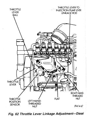
6- the linkage rod (figure 62 ) connecting the throttle lever to the fuel injection pump lever is adjustable to prevent damage to the ends of the linkage, attach locking type pliers to the flat (figure 62) located on the linkage rod before loosening lock nuts.
7- loosen the right hand thread nut (figure 62).
8- Loosen the Left hand threaded nut (figure 62).
9- Slowly rotate the flat (figure 62) on the linkage rod (lengthen or shorten) to achieve 1.0 Volts (within .2 volts) on the voltmeter with the linkage in the idle position. At WOT , the output voltage must be 2.2 to 2.9 volts higher than @ idle speed.
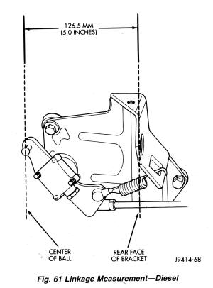
DO NOT LENGTHEN OR SHORTEN THE LINKAGE ROD MORE THAN 1 MM FROM THE DIMENSION SHOWN IN (figure 61) IF THE VOLTAGE REQUIRED CANNOT BE MET BY LINKAGE ADJUSTMENT (125.6 to127.6 mm) replace the TPS.
10- Tighten both nuts after adjustment
11- With the engine off, operate the throttle from accelerator pedal and check for throttle lever action and binding. be sure throttle lever stop is against the low idle speed screw after throttle is released.
12- Be sure of WOT when accelerator pedal is pressed to the floor. This is checked by observing the throttle lever brake over position. Proceed to the following:
- A- Key Off and engine off for this test.
- B- 2 people are needed for this test . From inside the vehicle, press the accelerator pedal about 1/2 way to the floor. Movement of both the throttle lever and the throttle lever to injection pump lever linkage rod (figure 62) should be observed.
- C- Continue to press the accelerator pedal to the floor. If throttle lever brake over is operating correctly, the throttle lever to injection pump lever linkage rod should of stopped moving while the throttle lever continues to move towards the rear of the vehicle.
13- Again check and verify low idle speed Adjust when necessary.

2 Trackbacks
[…] was at 1.25 and trans was bouncing in and out of gear all over the place. shifts great now. 12V Cummins TPS Adjustment | Diesel Database __________________ 1997 Dodge Cummins 12v , 120k mi, 4×4 , ext cab , DDP stage 2 75hp, #8 fuel […]
[…] linear power output, no dead spots or erratic readings) and make sured that it is set to spec. http://dieseldatabase.com/12v-cummin…ustment/?id=53 __________________ 97 Ram 2500 / 5.9ctd /NV4500/241DHD Custom Intake Tube+ BHAF, Pump Tuning, […]