
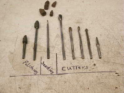
First, you will need cutters. In the next photo you will see some of the cutters I use for this. On the right are metal cutters. These cost $20 to $75 each, so choose wisely.
In the middle are sanding cones. I use #80-100-220-240 grit. I use a long mandrel and a (not shown) short mandrel.
On the left are my own design polishers. These are made from med and fine grit de-burr wheels. You may use emery cloth attached to a mandrel and get good results. You may even run it without polishing if you wish.
I do not polish to a mirror finish for street use since it will be covered with carbon after a few miles anyway. So use whatever drive you have and remember: GO SLOW!!! Think ahead. Once material is removed, it cannot be put back.
This pic shows the various wheels/cutters/deburs, etc.
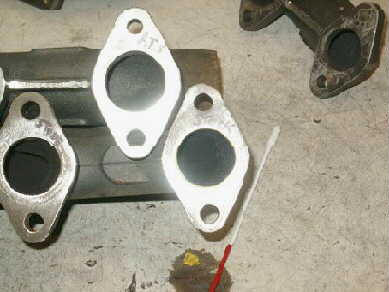
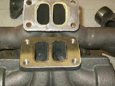
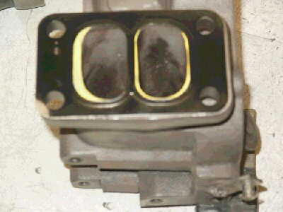
Now here you will see the difference between an ATS and a stock manifold to head flange. Notice the ATS is larger and the yellow mark on the stock one. The ATS can be left alone, but the stock one will need to be opened up to match the gasket. Why? because in order for the proper scavenge to take place, the manifold must be larger than the exhaust port. You never want to match the head to manifold exactly for a street driven rig, gas or diesel. This is flow science, folks, kinda like rocket science.
If you are running an ATS manifold, you need to know a few things. First and foremost, ATS does not finnish their product very well. And the 12 valve units are worse than the 24 valve. Never take anything for granted, check it all, mainly port match. I have seen some off by .200in.
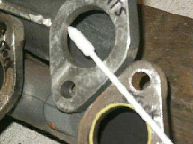
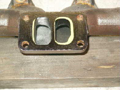
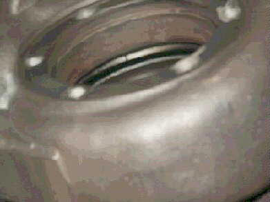
In this photo you see the inner radius of the port as the gasses enter the manifold. It is a 90 degree cut. THIS IS BAD!!! You will need to radius this as it is in the stock manifold. The stock ones are pretty close to being good. So just make it look and feel like the stock one. And yes, I said FEEL. You need to stick your finger in there and FEEL it to see if there are any sharp edges. Your finger should roll right around the corner and into the manifold.
Remember, it you have any questions or doubts, STOP and ask.
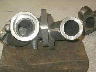
OK, I’m gonna pick on ATS some more. This is the “slip joint” from the inside. There is a miss-match here and it will cause a lot of confussion for the gasses as they try to find their way to the center of the manifold. Some are worse than others. BEFORE you put the manifold together, make sure this area is matched for better flow and lower EGTs
Now we are going to talk about the “heart” of the manifold. The center section. We will spend some time here because if you do nothing else, fix this. But remember what I said before, you can run a ported turbo on a non-ported manifold, but you cannot run a non-ported turbo on a ported manifold.
Here we see a stock (yellow markings) and a ATS turbo mount flange. Notice the amount of material that will need to be removed from the stock unit to get it to match the gasket. SPECIAL NOTE; LEAVE 1/8″ from the gasket to the port on the SIDES here. I will explain why later.
You want the aproach here to be as straight as possible the last 1/4 inch before it enters the turbo housing. (or leaves the manifold)
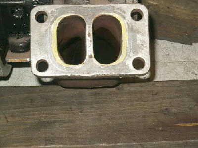
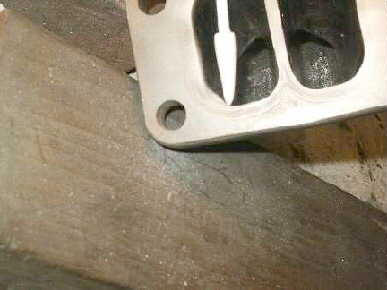
>Here is a photo of a stock manifold that has one side only opened up. I did not finish anything so the pictures will show up better on film. But you can see what I am talking about now. Notice the material left on the edges and straight lines.
Ok, now here is the hard part. What you want in the manifold is, Volume and flow in the runners going from the head to the center, and Volume and velosity as you go into the turbo. Double standards for a fixed piece of metal. Plus you want the gasses to make a double S turn. The top and bottom become the sides and the sides become top and bottom. All this while excelerating. WHEW!
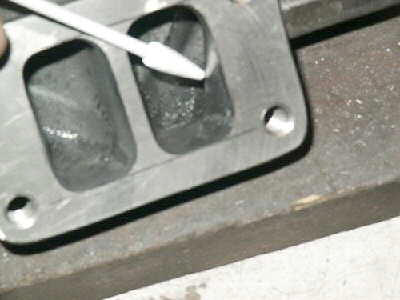
And here is what is making all this happen. The center section. The pointer is showing you a turn the gasses from two cylinders must go around to exit. This radius must be made less dramatic but constant and smooth. On the inside (head side) of this you need to make sure the ramp is a smooth radius also. You will see that these gasses must fight for right of passage as the inner cylinder runs right into it. RIGHT IN THE MIDDLE OF THE BEND. So just make sure there is no interference here. Make everything smooth and constant. Don’t be affraid to stick your finger in there and feel it. You must do this. Feel for any bumps or lips. This is the place where the gasses are speeding up even though they don’t want to. So you need to help them. Any confusion here causes heat and back pressure.
This is the most important part of the work you are doing so open it up and make it smooth. The runners and the center must be blended together before they exit the manifold. I do not have a photo of the inside as it would not turn out for some reason. So if you have questions, ask.
This is a 21cm2 turbo housing so the ports are larger than the smaller units. But you can see the material that must be removed. Remember me talking about leaving 1/8″ on the sides of the manifold? This is why. If you open up the housing to match the gasket, the wall of the housing will be very thin and could crack. You loose a little CFM but you don’t ruin a $350 housing. Good trade I think.
This is a pic of the turbo “bump”. These (there is 4) are located inside the housing and cause turbulence. You may cut these about .60″ but no more as the wall is thin here. If you don’t want to take the chance and cut them, at least rework the departure area so it is not a drop off. This will increase flow. The turbo housing has a natural taper to it and this is good. But you need to match the entrance to the housing as close as possible to the manifold to act as a venturi . This exelerates the gasses as it approaches the turbine. Match this area and polish it as best as possible. And go down inside as far as possible. If you don’t take the time to match this area, you are throwing away power and generating heat. The whole idea here is to lower back pressure to release the parasitic drag on the engine and to reduce heat. Heat is good in the combustion chamber, but not good in the exhaust. Also, if you have a 90 degree tool. you can polish the area where the gasses enter the turbine. This area is hard to see and if you can rework it, it helps a little also.
Ok, it seems the photo I had for this one is no good. But you can see what I am talking about by simply looking at your housing.
Now here is a good photo of what NOT to do. Some one ported this without even LOOKING at what they were doing. You can see the gasket on top and the mismatch of the ports of the housing. This housing can not be saved. It has been cut too far out. Remember when I said to take it slow?
Oh boy did I mess that one up. That is a photo of the same housing with the mismatch but with some more very bad news. After glass beading, this housing was found to have eleven (11) cracks in it. All you guys that think it’s funny to generate those high EGTs need to take a good look at this. When you run those temps up to the moon or pull a hill hard and back off, this is what can happen. Just emagin what will happen to your very expensive turbo when a chunk of cast steel falls into the empeller spinning at 140,000 rpm.
This photo shows the “bumps” in the exhaust housing. The pointer is pointing at one. Remember, the wall thickness is thin here, so don’t go crazy and remove too much. If you want to play it safe, just polish it well.
[thanks to nwbombers.com and hdm48 used with permission]